 Image 1 of 4
 Image 2 of 4
 Image 3 of 4
 Image 4 of 4
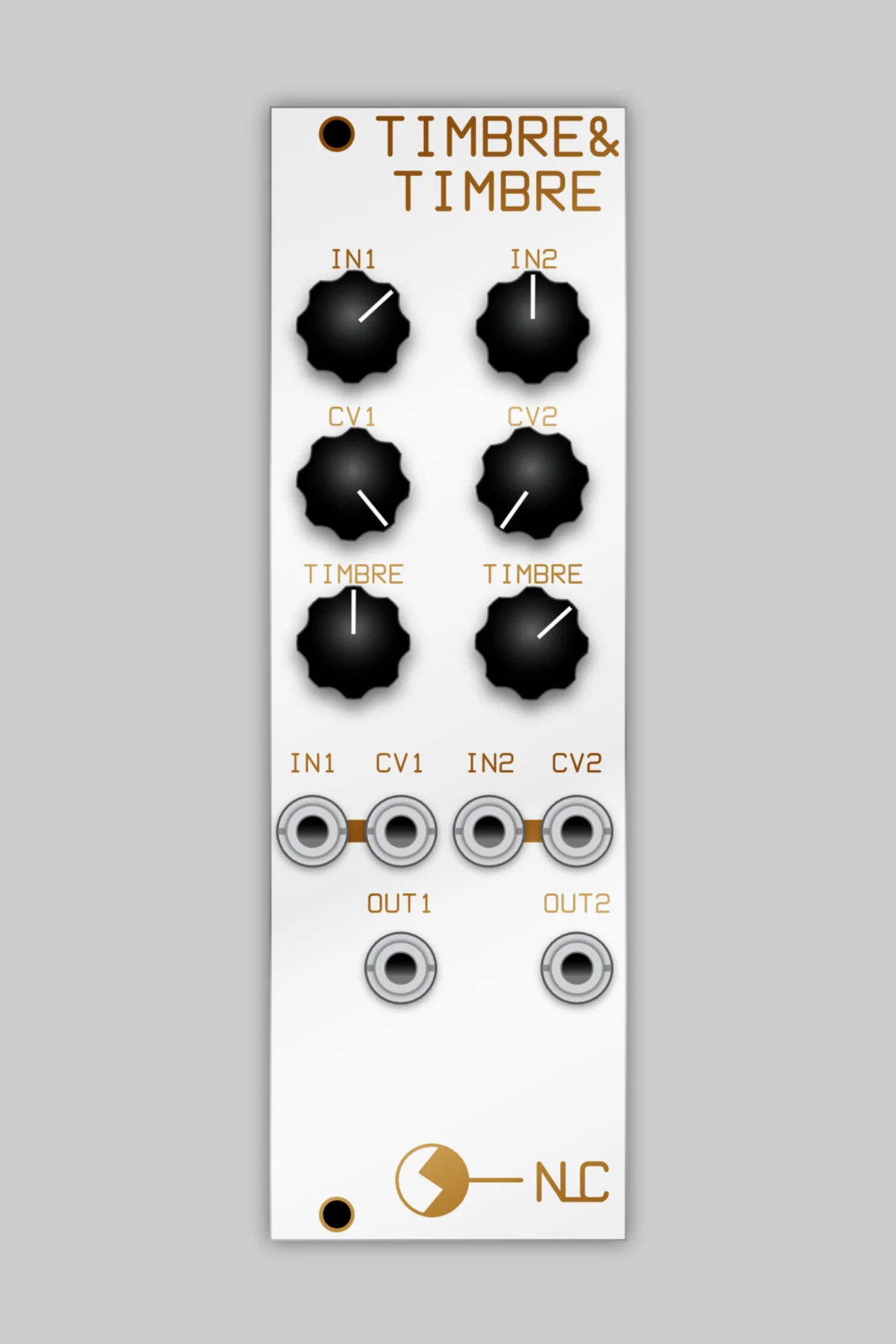
8hp
This is simply a dual version of the Timbre!, which was based on the Buchla circuit. It is all smd (the single version is thru-hole) and the tri2sin circuit has been dropped, there is an input attenuator for each section.
The only changes to the original version are to fit the signal levels to Eurorack standard. The circuit will deliver some noise when there is no input signal so it is best to patch it directly to a VCO or patch a VCA downstream. The original Buchla Timbre was the waveshaping section of a VCO so there was always an input signal.