 Image 1 of 4
 Image 2 of 4
 Image 3 of 4
 Image 4 of 4
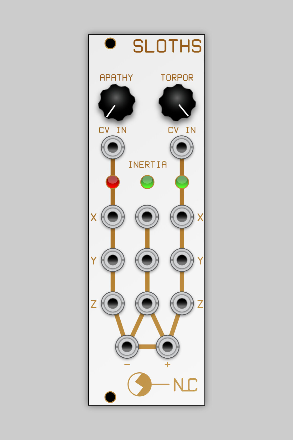
8hp
This module contains 3 Sloth chaos circuits. Each one runs at a different rate; Torpor takes approx. 15-30 seconds to travel around 2 strange attractors, Apathy takes 60-90 seconds and Inertia takes 30-40 minutes.
There are no controls for Inertia, it does what it wants.
The pots for Apathy and Torpor do not specifically alter the frequencies, rather the weight of the outputs. Various settings will cause the signals to spend more time traveling around one strange attractor rather than the other.
Apathy and Torpor also have CV inputs. Sometimes the CV signals are injected onto the chaotic signals but depending upon conditions may cause windows of periodicity or voltage jumps. Generally the results are good.
The X, Y & Z outputs for each Sloth are taken from different stages of the circuit and are all different to each other, although Z is simply the inverted version of Y. The three Z outputs are also fed into a Difference Rectifier and the results of this are available from the + and – outputs at the bottom of the panel. The Difference Rectifier outputs are (ignoring diode voltage drops):
out + = VApathy +VInertia - VTorpor If greater than 0, otherwise 0
out - = VApathy +VInertia - VTorpor If less than 0, otherwise 0