Description/Usage
8hp
This VCF uses two SSI2144 chips, which are based on ladder filters. It has outputs for each chip and a mixed output. Controls include the usual cutoff and voltage-controlled Q, along with ‘spread’ controls for cutoff and Q. If nothing is patched into the spread controls, the spread pots work as manual controls. So keep them on or close to zero if you don’t want any or much spread.
The spread controls work best with a bipolar CV (as in ranging from -5V to +5V), an inverted version of the spread CV is sent to filter core 2, so it changes in the opposite direction to core 1. The spread controls are meant to be a bit less influential than the main 1V/oct CV inputs, in tech terms it is approx. 1V per 2 octaves.
Check the Parts section for SSI2144 chips, I will try to keep them in stock.
So, I guess it is a stereo filter in some respects, tho it was never really the intent.
DIY
Build guide / BOM (pdf)
Panel Template
Solder paste Stencil
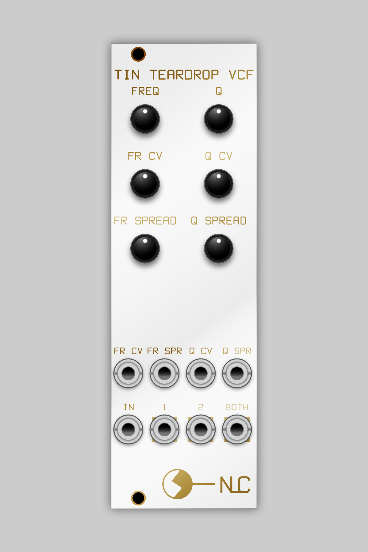 Image 1 of 7
 Image 2 of 7
 Image 3 of 7
 Image 4 of 7
 Image 5 of 7
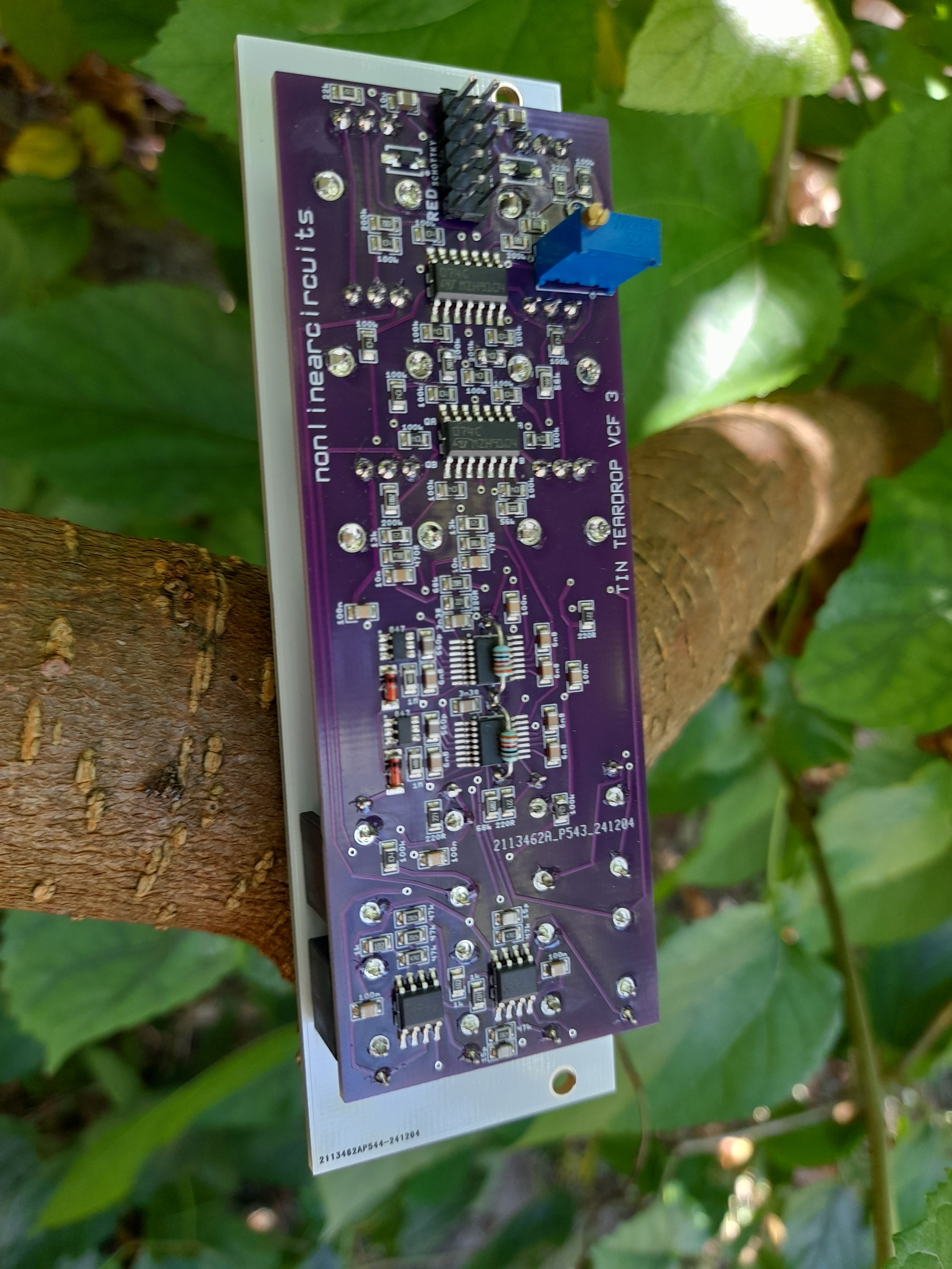 Image 6 of 7
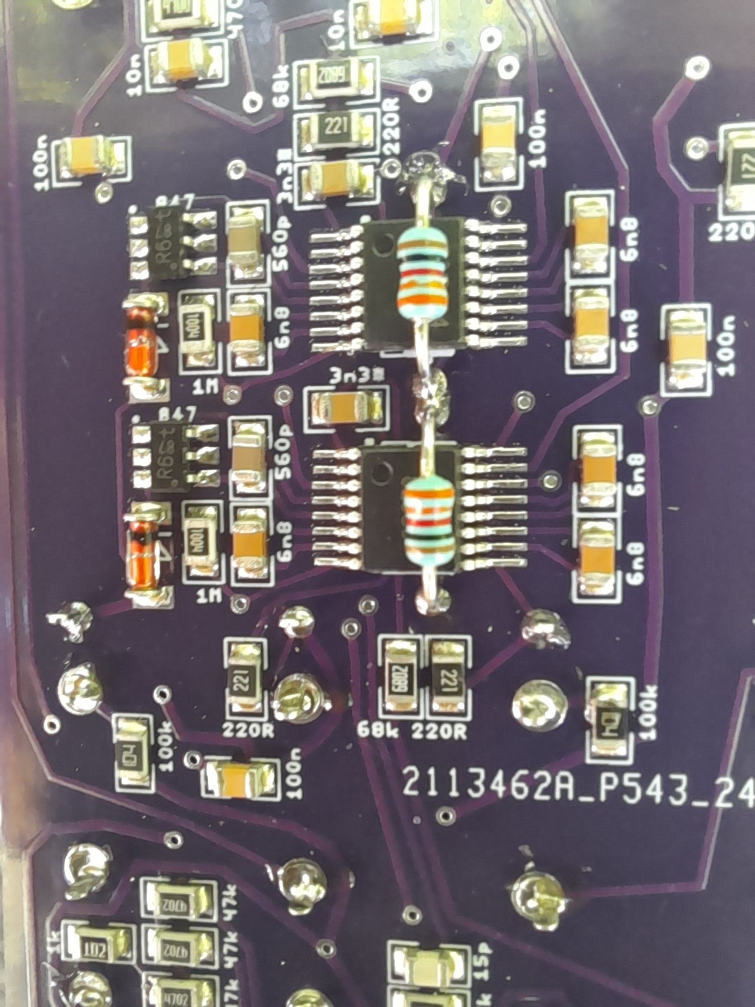 Image 7 of 7