 Image 1 of 4
 Image 2 of 4
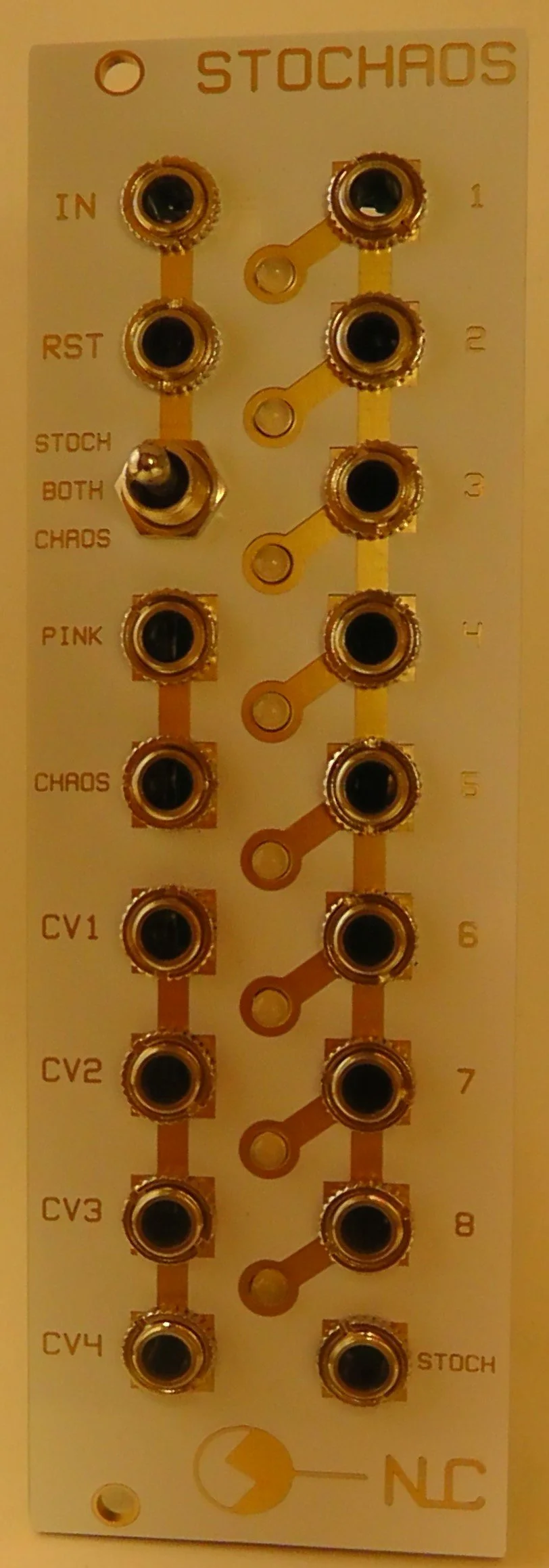 Image 3 of 4
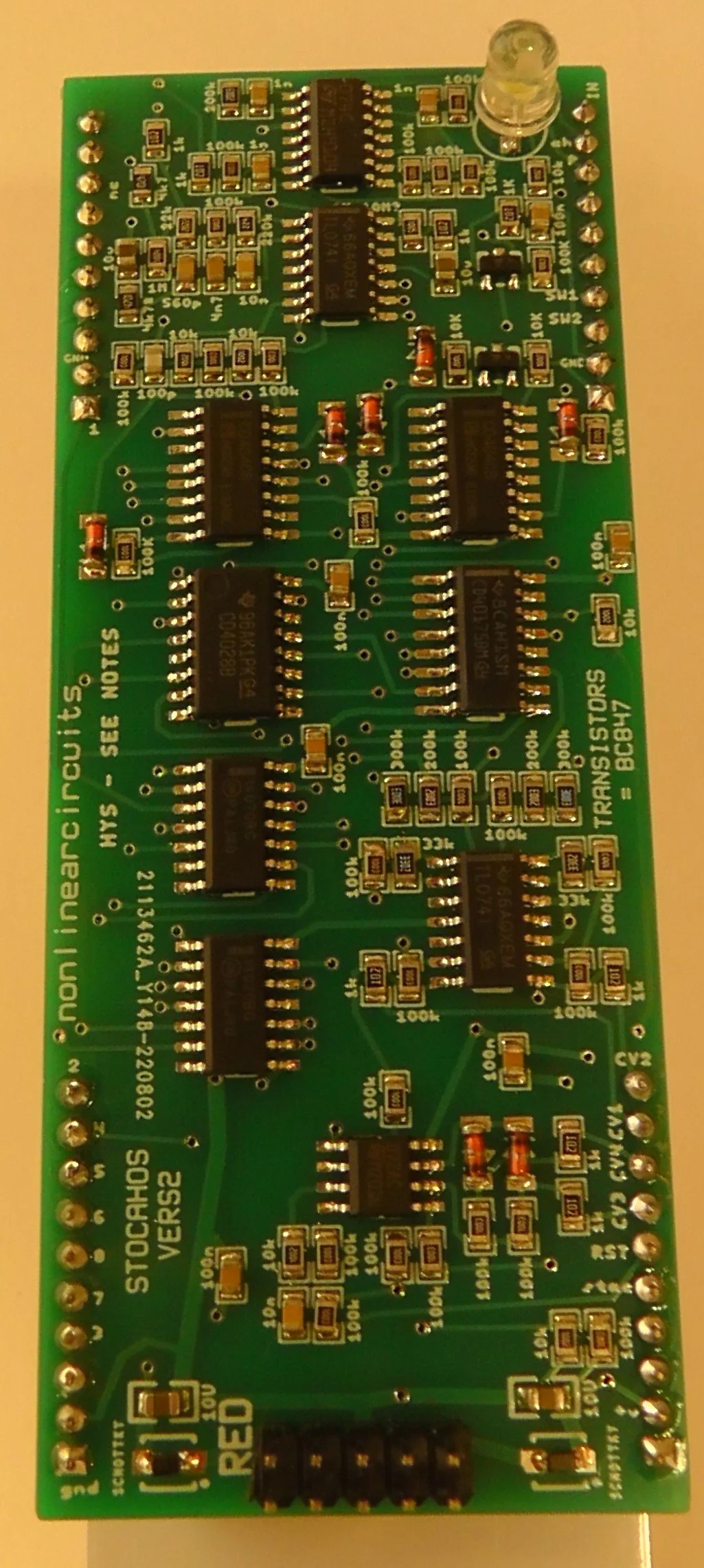 Image 4 of 4
8hp
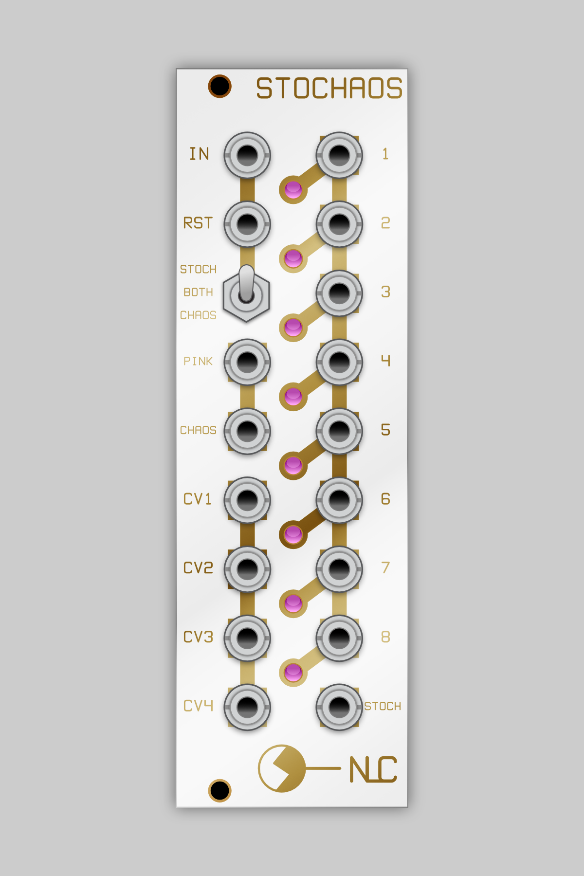
This module generates gates and control voltages based on pink noise or chaos or pink noise vs chaos. You can use a switch to select which variation. It uses a lot of cmos but I was careful to select chips that are still in stock at most retailers.
The base idea for the circuit came from a 1980 patent: US4208938 Random Rhythm Pattern Generator.
To operate, just feed a gate to IN, add a reset if you like. Select if you want full random (STOCH), chaos or random vs chaos (BOTH).
Everything else is an output. PINK and CHAOS are drawn off the internal random and chaotic sub-circuits.
CV1 And CV2 are fed to a difference rectifier to get CV3 and CV4, so CV3 will be mainly negative voltage.
1-8 are gate outs, so is STOCH. I had a spare jack so just routed an output from one of the earlier stages in the circuit, it tends to give longer gates than the other stages.
Assembled modules are built to order. They will be ready to ship within 4 weeks after ordering.
8hp
This module generates gates and control voltages based on pink noise or chaos or pink noise vs chaos. You can use a switch to select which variation. It uses a lot of cmos but I was careful to select chips that are still in stock at most retailers.
The base idea for the circuit came from a 1980 patent: US4208938 Random Rhythm Pattern Generator.
To operate, just feed a gate to IN, add a reset if you like. Select if you want full random (STOCH), chaos or random vs chaos (BOTH).
Everything else is an output. PINK and CHAOS are drawn off the internal random and chaotic sub-circuits.
CV1 And CV2 are fed to a difference rectifier to get CV3 and CV4, so CV3 will be mainly negative voltage.
1-8 are gate outs, so is STOCH. I had a spare jack so just routed an output from one of the earlier stages in the circuit, it tends to give longer gates than the other stages.
Assembled modules are built to order. They will be ready to ship within 4 weeks after ordering.