Description/Usage
8hp
This module contains two BBD based Flanger circuits. One is set by a pot, the other is voltage controlled (or just set by a pot). The intention is to create a thru-0 effect as the voltage controlled Flanger shifts to have longer/same/shorter delays in relation to the fixed one.
The design is partly based on the Infinite Flanger by Paul Williams published in Home & Studio Recording, September 1985.
The Mix pot determines the ratio of input signal and fixed Flanged signal fed to the output, the Anti-Phase switch feeds this to the inverting or non-inverting inputs of the output op amp. These two controls, along with Feedback, combine to give a great variety of different effects and sounds.
The LED indicates the clock activity of the two VCOs that drive the BBD chips. If you use a red/green LED, when it turns yellow the VCOs’ frequencies will be close to each other.
The module uses two SSI2100 512 stage BBDs, these can handle a clock rate up to 2MHz. The anti-aliasing filters are set for 15kHz. The two VCO chips (LTC6990) are set to run between 30kHz and 500kHz. If you prefer a higher rate, leave off the 1M resistor between pin 4 and pin 5, replace the 100k resistor, between pin 4 and Gnd with a link, this will give a range of 60kHz to 1MHz. No doubt you can do some fancy Karplus-Strong shenanigans if you patch an output to a low pass filter and back to one of the inputs. The two outputs are the same btw.
I can’t decide which rate I prefer, the higher rates result in some pretty unusual sounds, but the lower ones do too.
There is also a SA571 compandor to help reduce clock noise feed-thru.
I will prepare Shaver care packages of the unusual chips (2x SSI2100, 1x SA571, 2x 6990 VCO chips), will be in the Parts section.
DIY
Build guide / BOM (pdf)
Panel Template
Stencil template (gerbers)
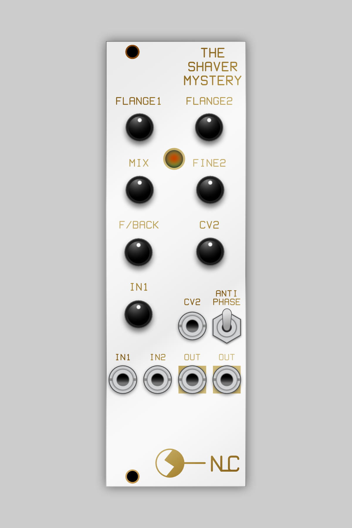 Image 1 of 9
 Image 2 of 9
 Image 3 of 9
 Image 4 of 9
 Image 5 of 9
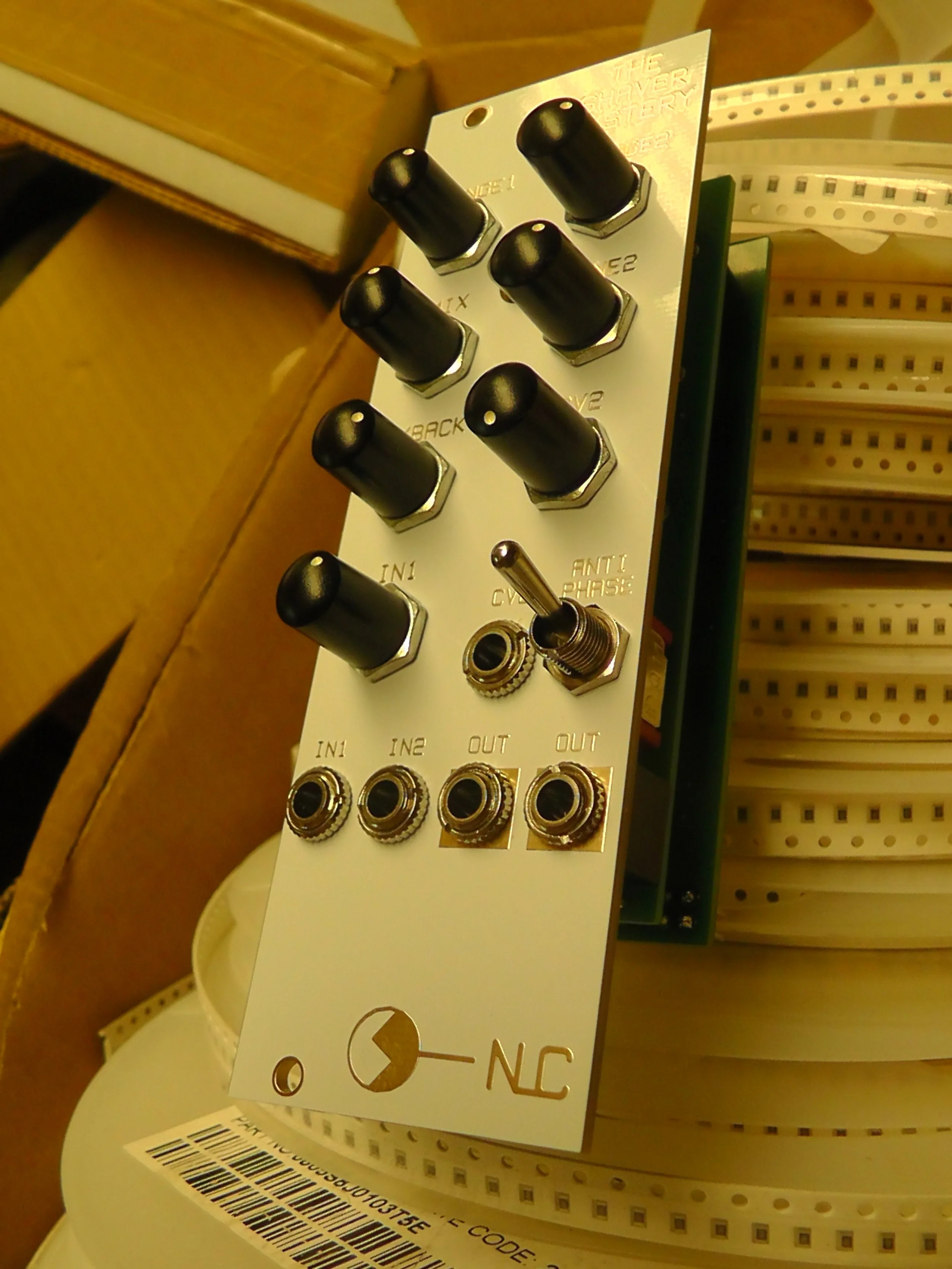 Image 6 of 9
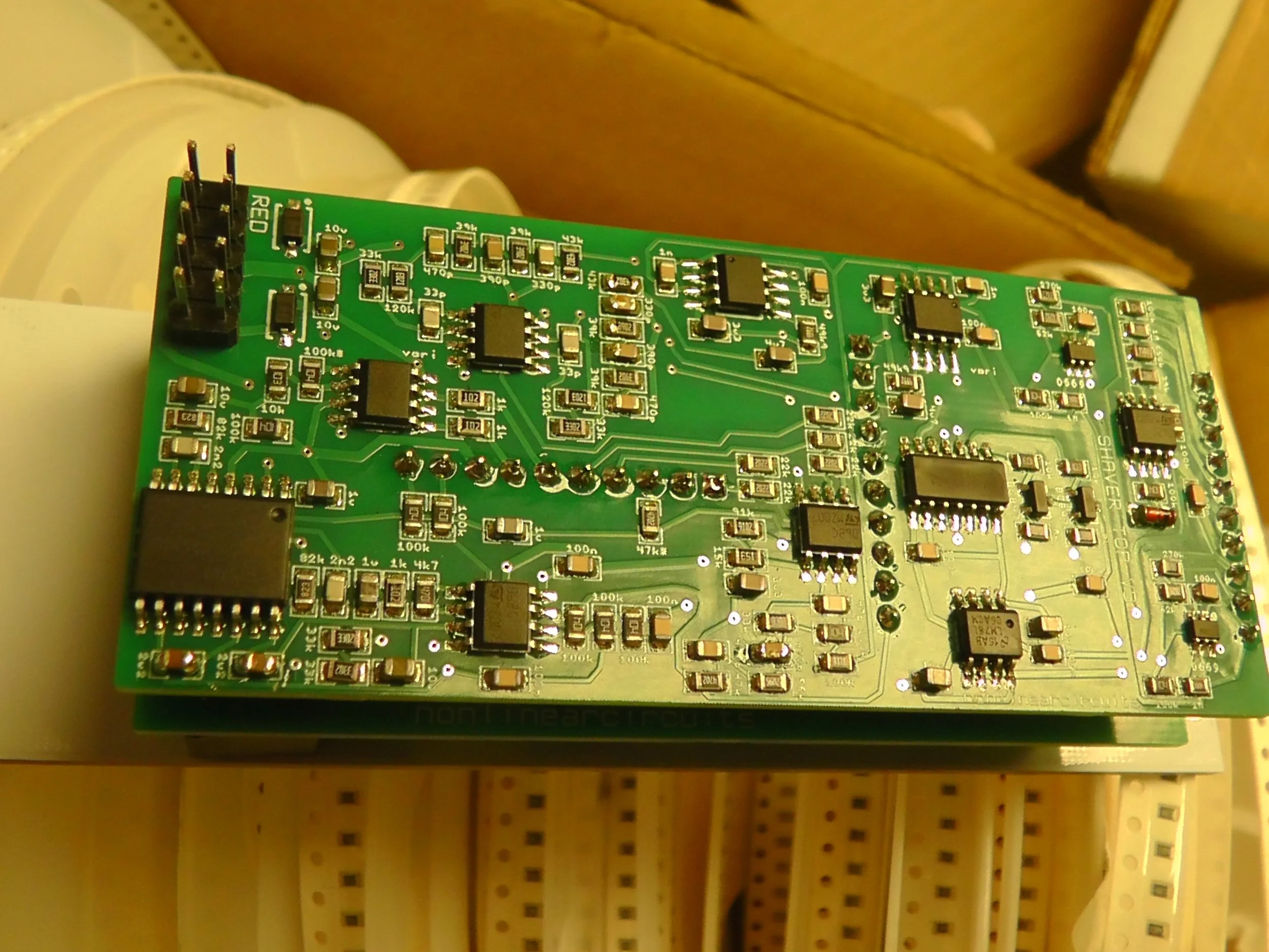 Image 7 of 9
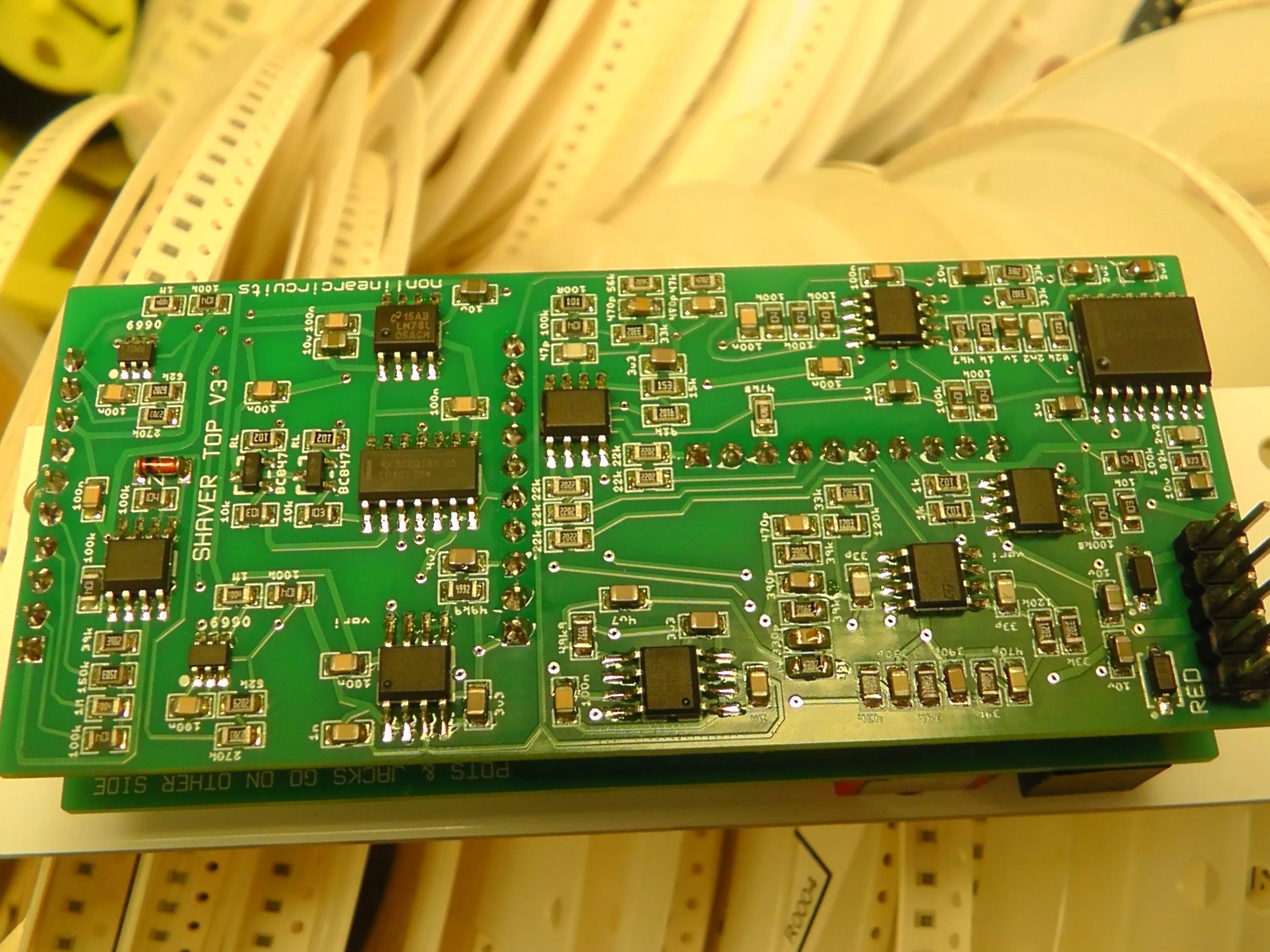 Image 8 of 9
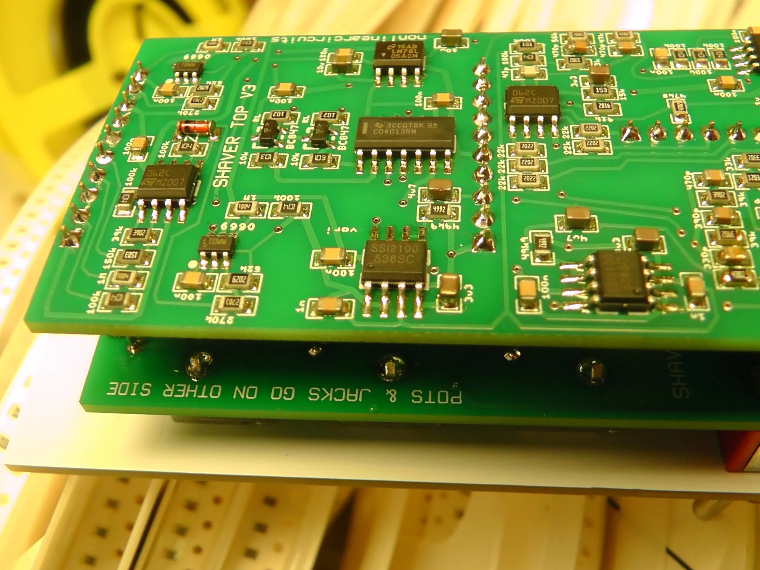 Image 9 of 9