Description/Usage
24hp
This module is a set of 4 reverse sigmoid chaos circuits, running at different frequencies, there are pots to feed each section into another and influence, sync – sort of, the action. There are also CV inputs for each section which affect the reset or crossover timing, for the faster ones the results are obvious. For the slower ones, give it a few hours.
The reverse sigmoid circuits are similar in concept to the mackey-glass based design used in the NLC Frisson, but are greatly simplified to a bare minimum of parts. Simply an integrator, two all pass filters and a nonlinear stage with two feedback paths. The nice thing about them is you can use any capacitors you like, so long as all three are the same, and the circuit will work with no other mods required. The sections in this module use 1uF, 10uF, 2x 1000uF in series (so 500uF) and 2x 2200uF in series (so 1100uF).
They work quite differently to the Sloth chaos circuits, with a number of ripples or rolls between each attractor, also the three outputs track each other, the faster ones are delayed by a few seconds, the slower ones by minutes. The intent of having 4 different circuits running together with pots to get them to influence each other is to have a module that can create longer tracks with many different but related musical events happening and, of course, weird delayed CV effects. Think of a band where the members all do their own thing but every now and then the sounds and patterns connect and achieve structure, which slowly scatters and reforms in new ways.
Feel free to change the 1uF caps to a higher or lower value, similarly for the 10uF. Stack capacitors on top of each other to get 20uF, or use Tayda 22uF caps and stack them. See pictures on pg6 for info on which caps to change. Make sure the capacitors have at least a 25V rating or higher.
If you want to use larger values than 1000uF and 2200uF, make sure they will fit on the PCB and/or thru the panel holes (1000uF on PCB are 10mm diameter, 2200uF panel holes are 16.8mm)
There are also two difference rectifier circuits which output complex mixes of the individual chaos circuits.
Demo coming soon.
DIY
Build guide / BOM (pdf)
Panel Template
Stencil Gerbers
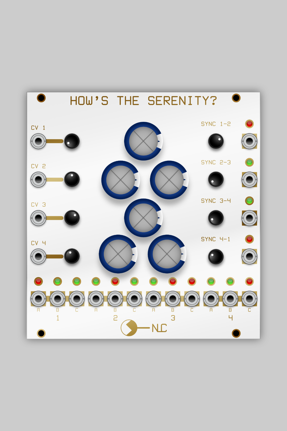 Image 1 of 9
 Image 2 of 9
 Image 3 of 9
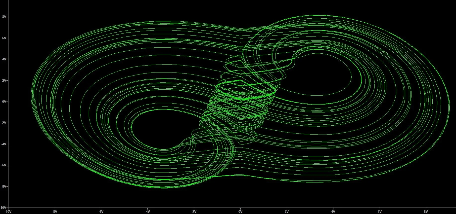 Image 4 of 9
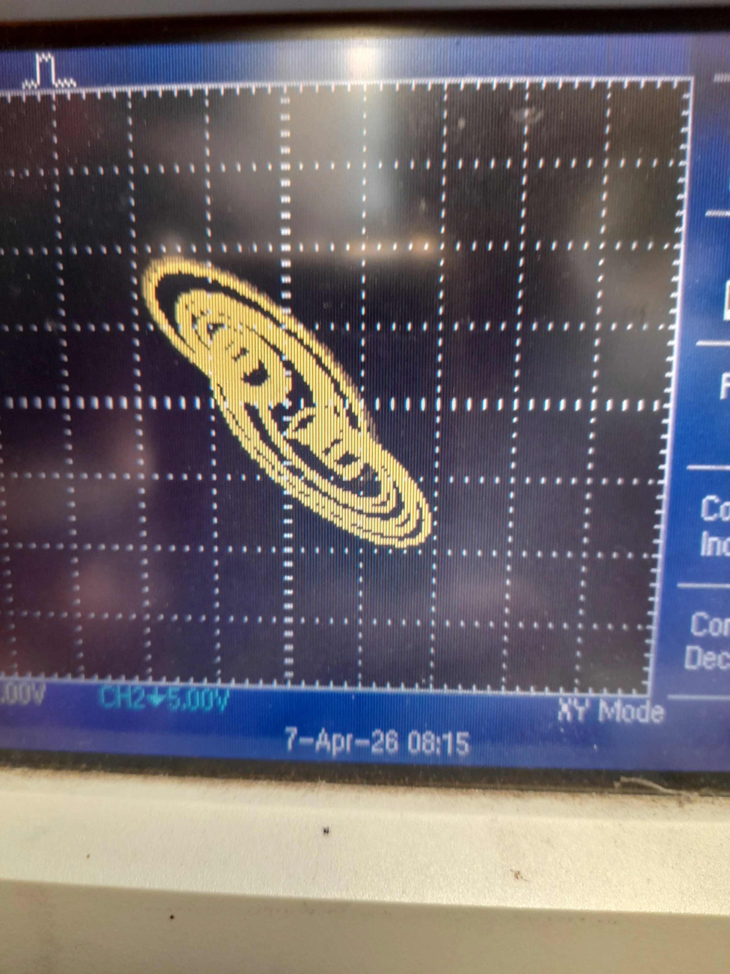 Image 5 of 9
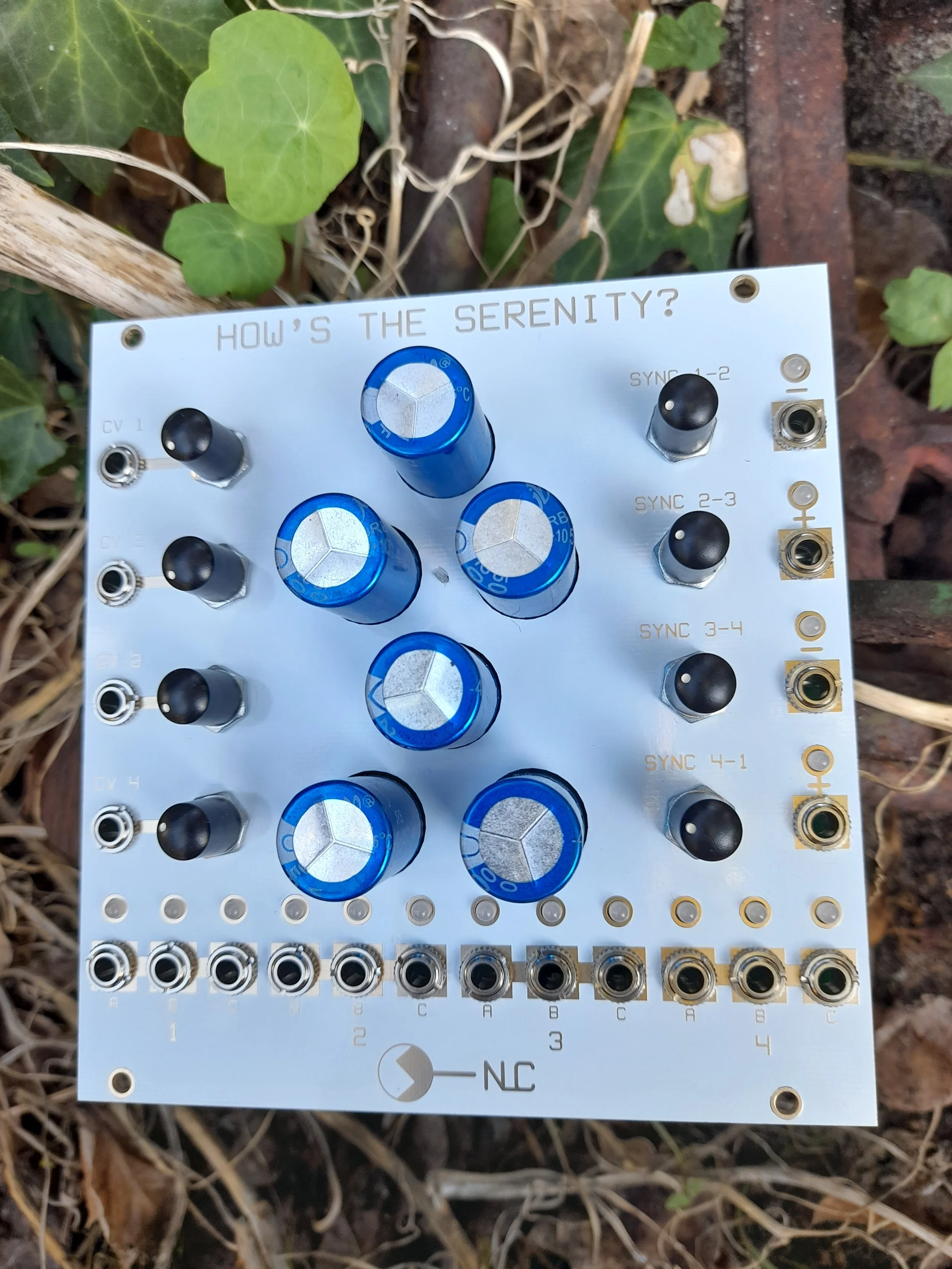 Image 6 of 9
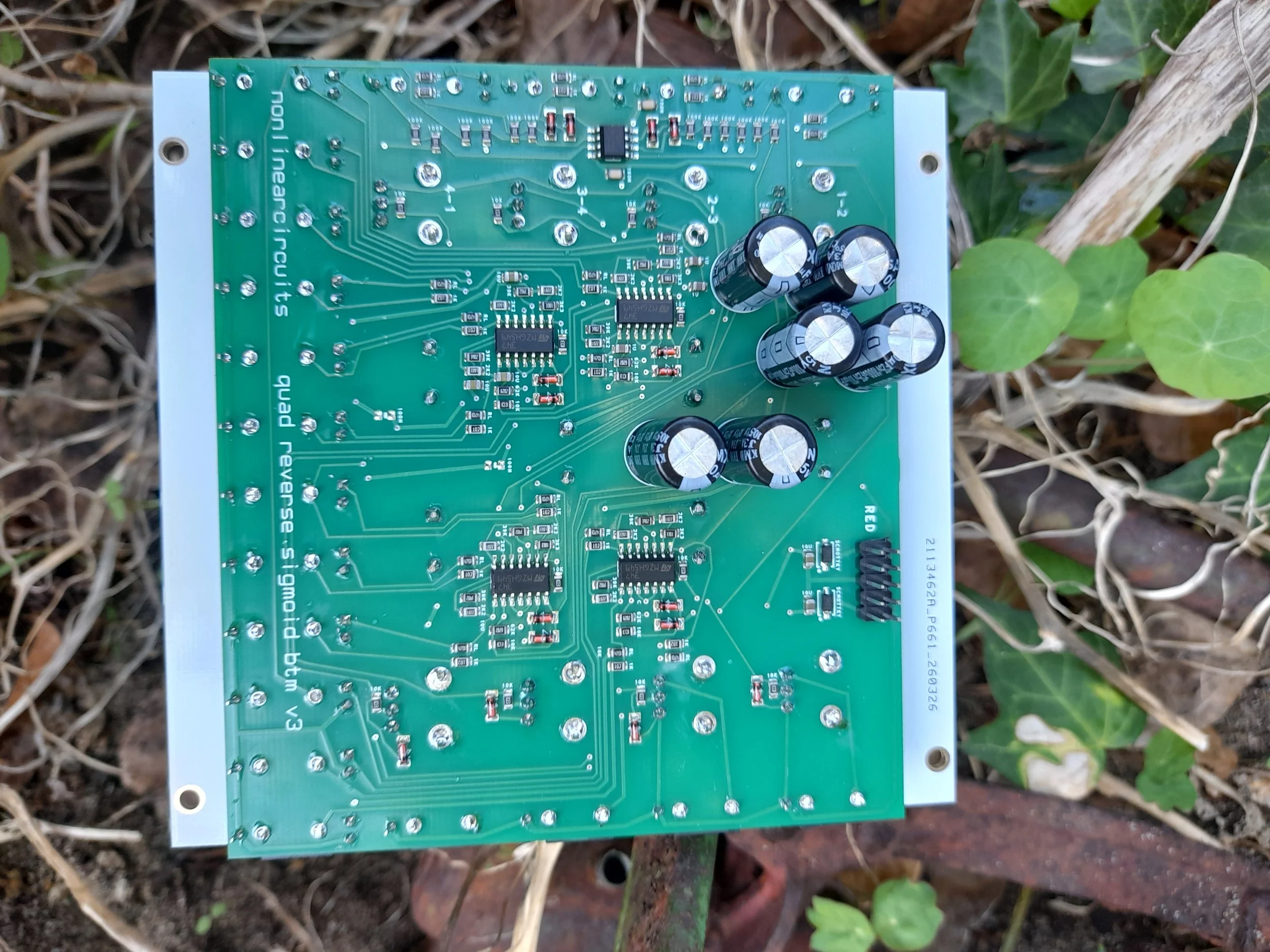 Image 7 of 9
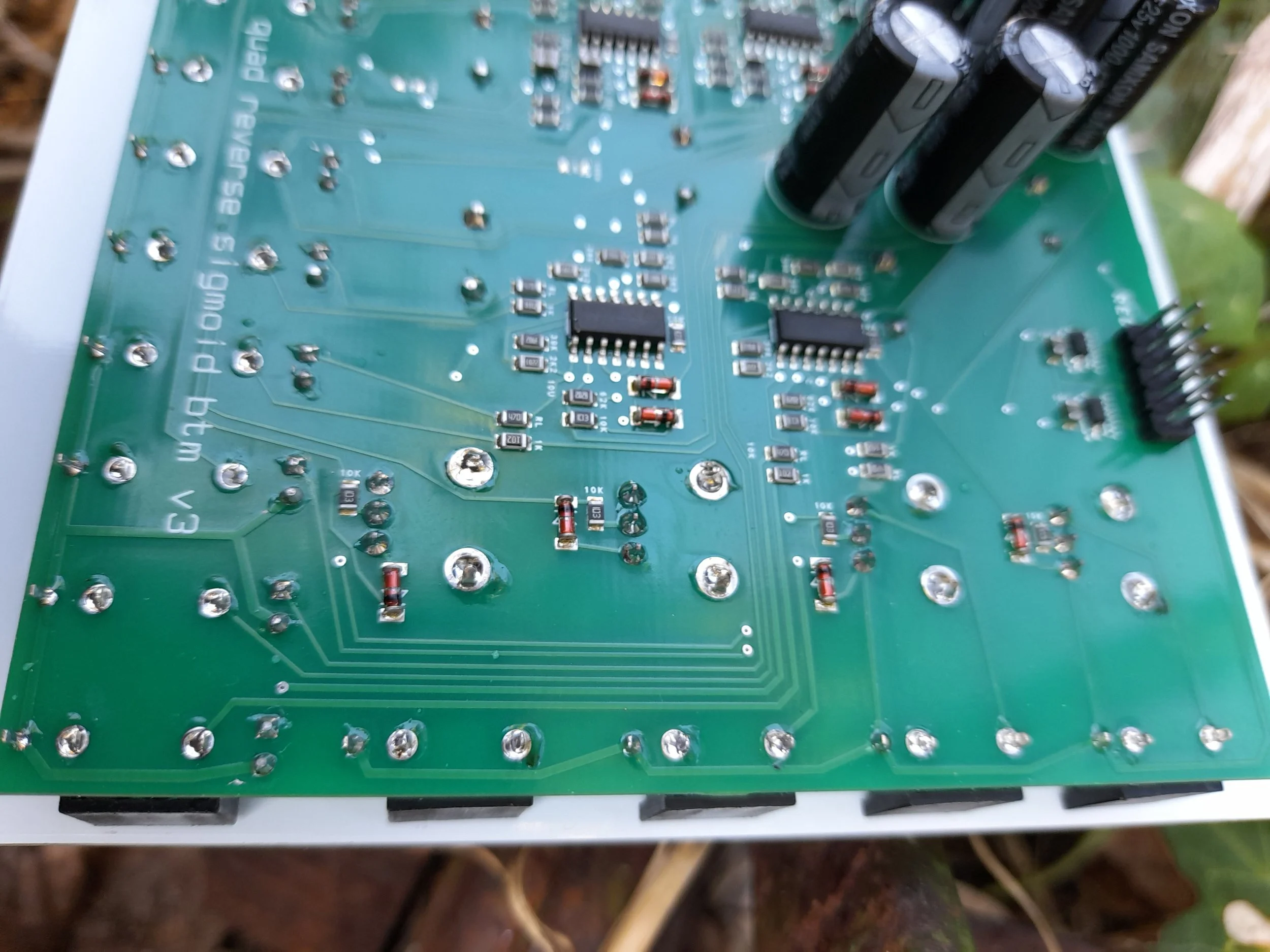 Image 8 of 9
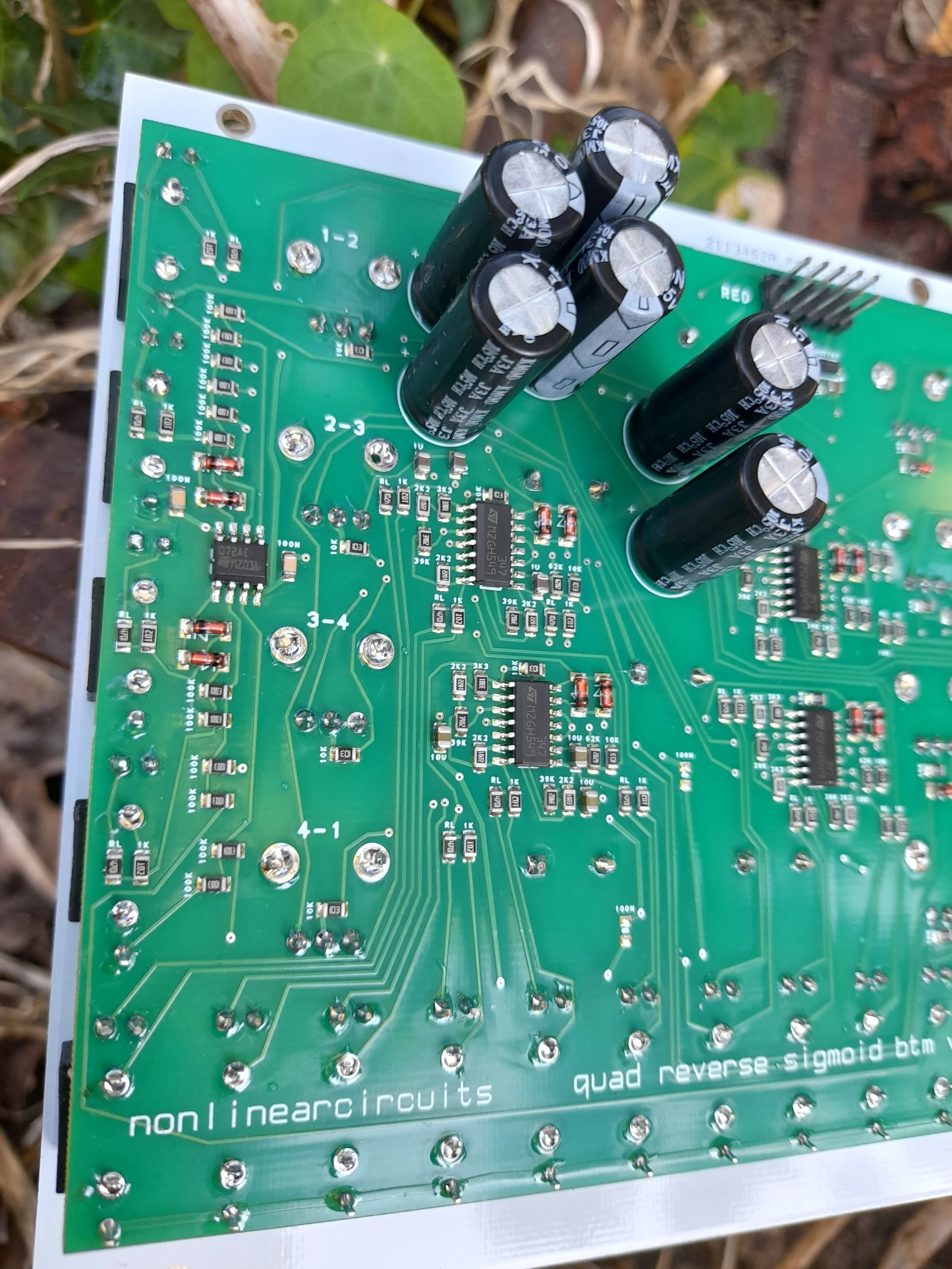 Image 9 of 9