 Image 1 of 3
 Image 2 of 3
 Image 3 of 3
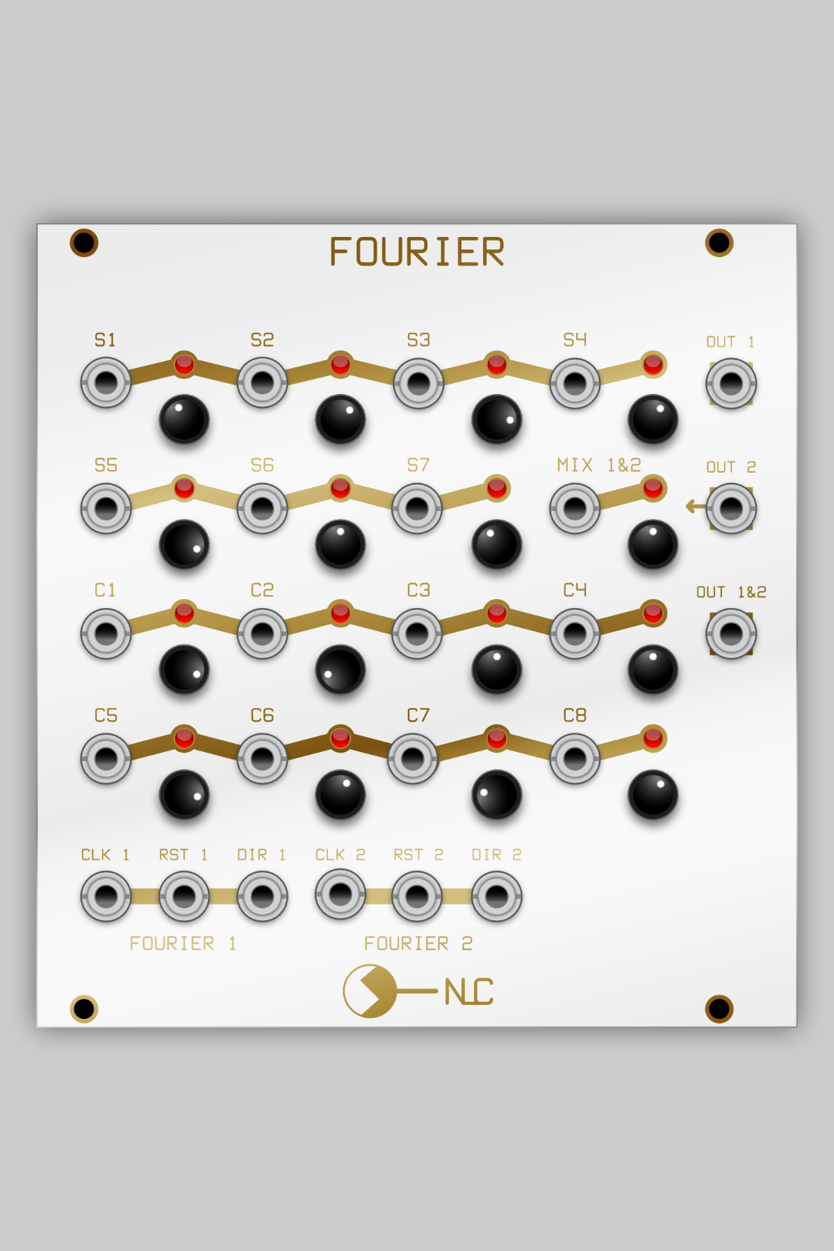
24hp
This module is based on an article presented by E. Muller (Jan 1983 Elektor link to archive.org) in the “Ejektor” section, meaning it is an imperfect but interesting idea (my italics). Of course, I had to try it and to my surprise, it sounds wonderful. If you are into shifting soundscapes and drones, this is a great tool. Probably best to check out the original article for the description.
It follows the basic principles of Fourier Synthesis, with a bit of Walsh thrown in, the pots (or inputs) allowing control of 7 sine and 8 cosine signals, supposedly being harmonics of the initial signals. “Supposedly” because, the waves are not pure sinewaves, rather stepped pulse waves.
This module needs to be patched into a low pass filter (ie – almost any VCF) for normal use, tho feel free not to and try something else. I didn’t bother installing a VCF onto the module because pretty much everybody already has one in their case.
To use, it usually needs a fast clock signal from a VCO. Fast means 16x faster than what you want to hear. This clock signal is fed into a multiplexor….multiplexer…..mux which scans thru the channels and feeds the signal to the output. There are two MUX, which can be operated independently otherwise channel 2 is fed a clock signal at half the rate of whatever channel 1 is getting. Channels 1 & 2 outs are available individually and mixed, with a pot to set the channel 2 level so it acts as a sub-harmonic source (or an external signal can be mixed in instead of channel 2).
It can also be fed a slow clock signal and be used as a somewhat strange sequencer/patter generator.
Each channel has its own reset and direction inputs to mess with proceedings as you wish.
Each pot (or input) is fed to multiple channels to create the harmonics for each stage. As the pots are wired between +/-12V, they are cut out of the circuit when an external signal is patched in, so do not work as attenuators, just as presets or nothing.
It gets very interesting to patch CVs into the harmonic inputs, especially nice slow ones from Sloths or LFOs. Audio signals are good. Using white noise is fun. Using white noise as a clock source is very interesting too.
It looks a big build, but is not too hard. The resistor matrix only uses 3 values, so it is not like you have to hunt around for many different obscure components.