 Image 1 of 5
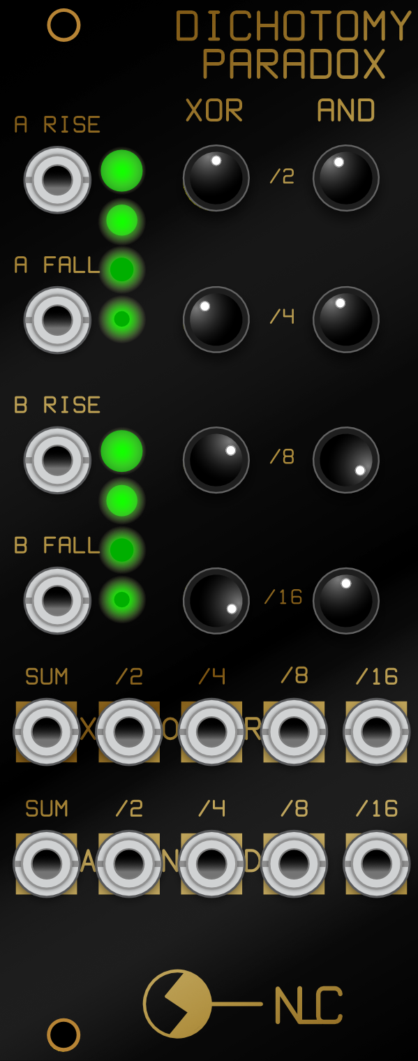 Image 2 of 5
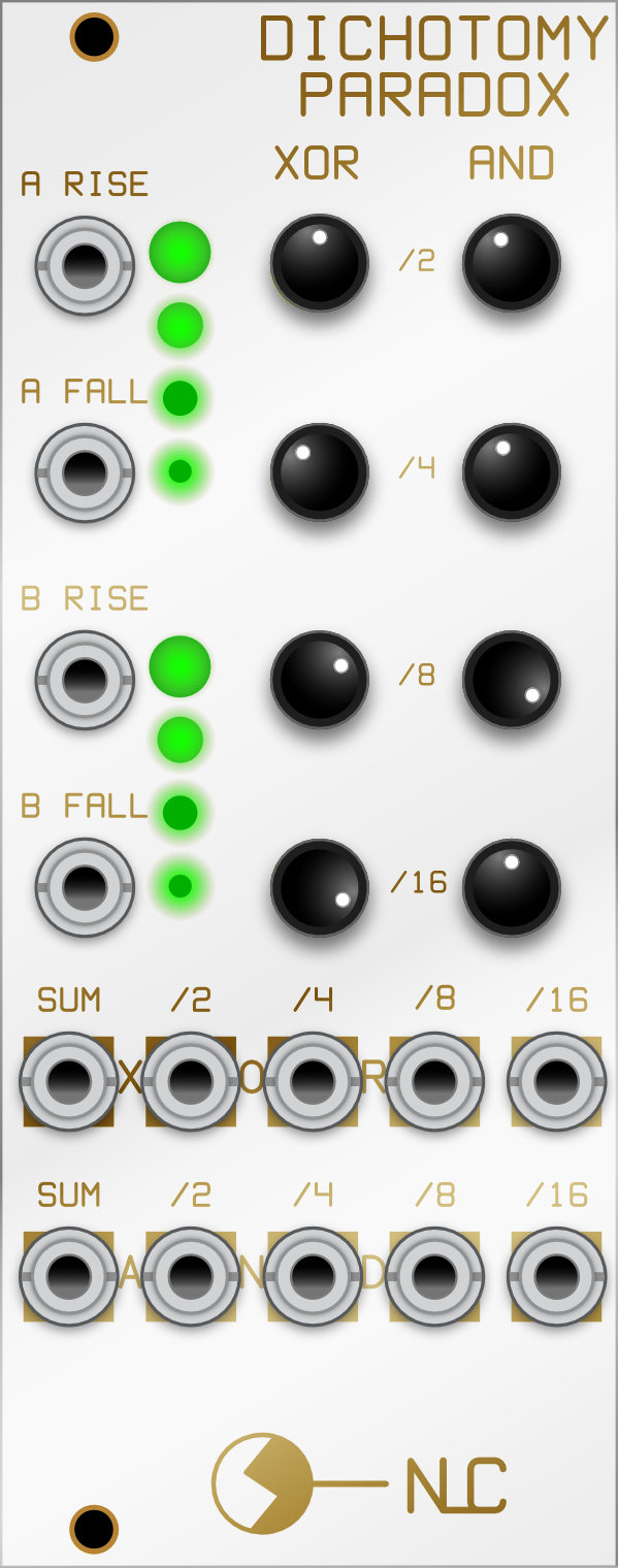 Image 3 of 5
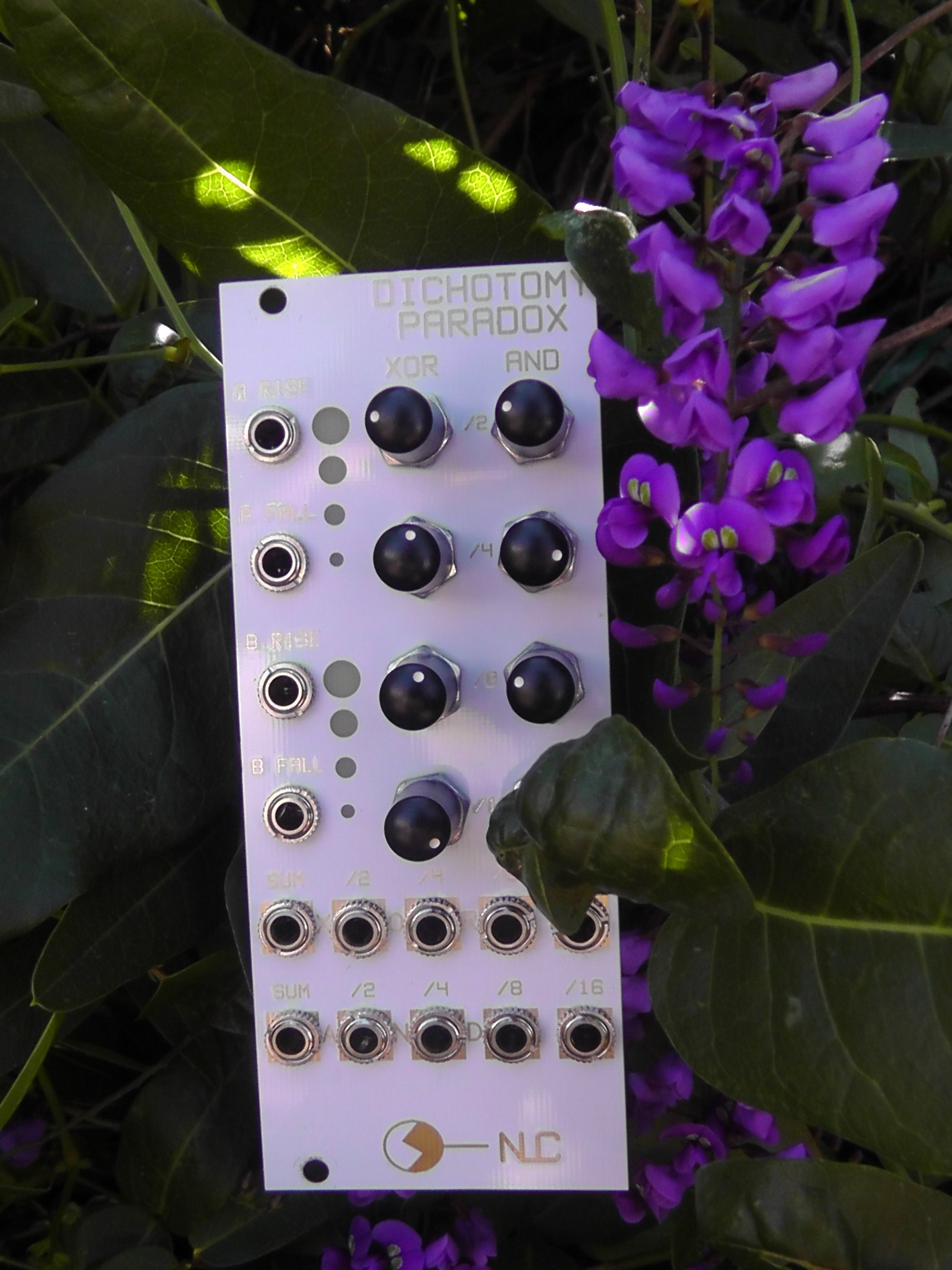 Image 4 of 5
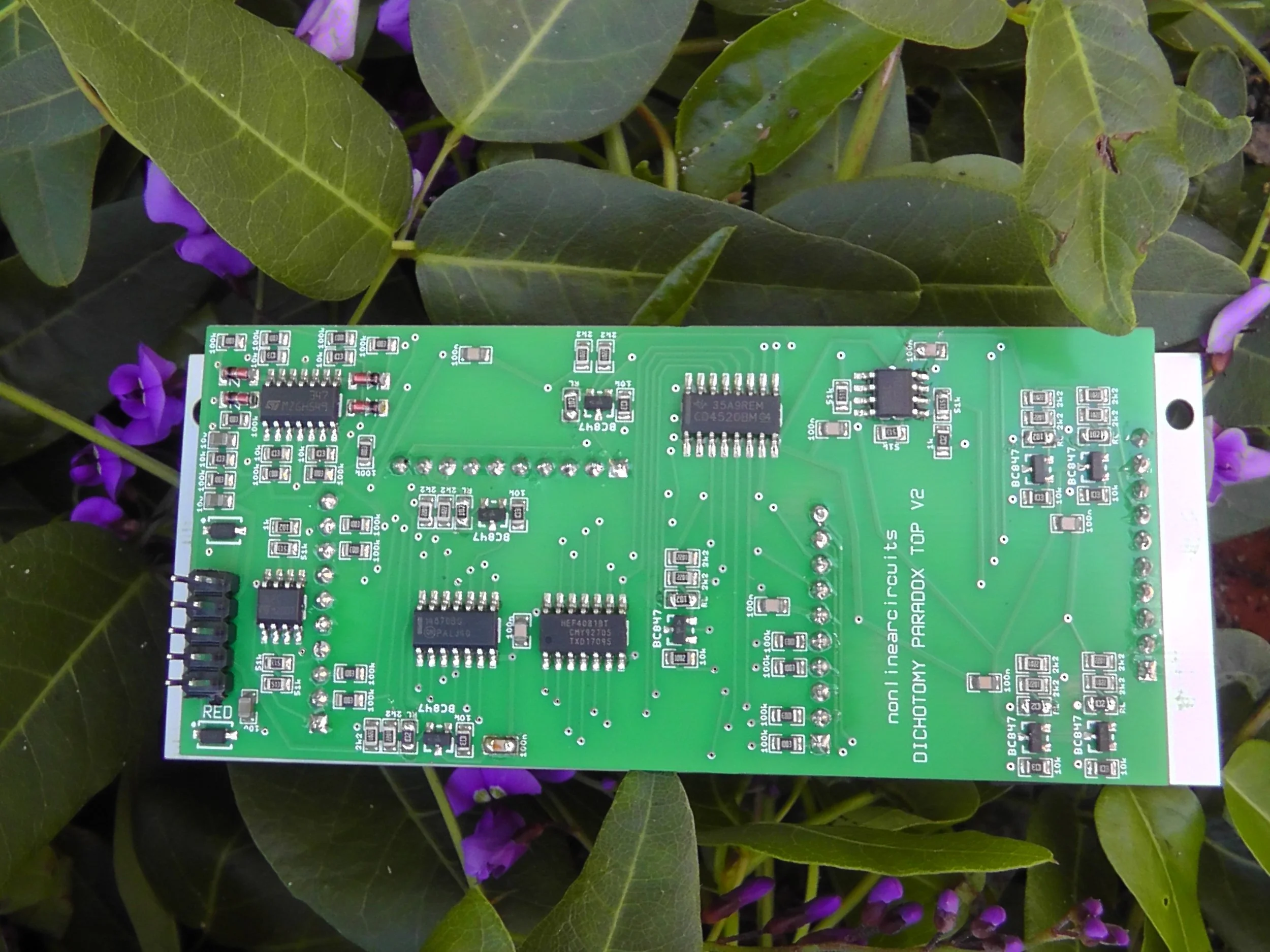 Image 5 of 5
10hp
This module has been thru a few cycles. The original idea for the design is from an article in Electronotes EN#98 by Lester Ludwig, spectacularly titled ‘A Square-wave Frequency-division Sub-octave Cross-product Module, it’s relationship with Lie algebra, and other related processes’ or more simply known as The Cross Product Module.
The frequencies of two VCO signals are separately divided by /2, /4, /8 & /16 ratios. The corresponding divisions are ANDed together and the results, along with all the raw divided frequencies are mixed together in various ways. You end up with a very harmonically thick, animated sound.
I did a full bloat CMOS (Ludwig’s design was TTL) version for a 4U panel back in 2008 or so, but changed the AND gates to XOR gates for a more ring-modulated effect. Then a minimal, slimmed down eurorack version, called Divine CMOS. This just used the XOR’d signal and outputted a signal determined by the pots.
After some requests for an expanded version, I re-visited the design.
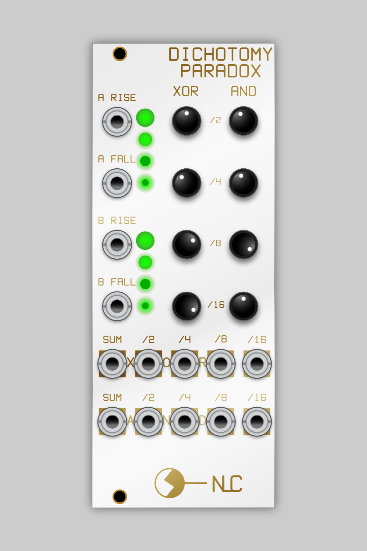
Dichotomy Paradox (from Zeno of Elea) has both XOR and AND channels, with gate outs of each division.....ok, sub-octaves... and mixed outs set up by the pots. It can be used as a complex pattern generator if fed gates or it can be used to create rich, animated audio sounds.
A big change with this version came from having a closer look at the 4520 dual divider chip (properly – a dual 4-bit internally synchronous binary counter).Each counter has two clock inputs, one triggers on a rising edge, the other on a falling edge. The intent is for one input to be a clock input and the other is an Enable, but don’t feel limited by that. All four of these inputs are available on the panel and can be used for all sorts of glitchy, stuttering shenanigans.
Feed your clock into the Rising edge and use the Falling edge input as an Enable control with gates to turn the dividers on and off (or vice versa).
Feed a Tri or Sine into one Rising input and mult the signal to the Falling input of the other channel. Then add another signal to the Rising input of that channel.
Feed in 4 different signals from different VCOs, for audio, or gate sources for pattern generation.
For audio, signals that are very close in frequency, say one is slightly detuned, give really interesting results. Of course, don’t let that stop you, do whatever you like.
One point to keep in mind; the pots act as attenuverters.Centre is off, turn to the left to send the signal into negative voltage territory and to the right for positive.
If feeding just one of the sub-octave signals into SUM, the pot will allow the signal to go to +5V or -5V at max or min settings. When you start mixing in other divisions, the signals are summed, meaning you can get outputs from sum ranging between -10V and +10V. Good times! If you prefer your signals are bit more tepid, don’t turn all the pots to max or min.
10hp
This module has been thru a few cycles. The original idea for the design is from an article in Electronotes EN#98 by Lester Ludwig, spectacularly titled ‘A Square-wave Frequency-division Sub-octave Cross-product Module, it’s relationship with Lie algebra, and other related processes’ or more simply known as The Cross Product Module.
The frequencies of two VCO signals are separately divided by /2, /4, /8 & /16 ratios. The corresponding divisions are ANDed together and the results, along with all the raw divided frequencies are mixed together in various ways. You end up with a very harmonically thick, animated sound.
I did a full bloat CMOS (Ludwig’s design was TTL) version for a 4U panel back in 2008 or so, but changed the AND gates to XOR gates for a more ring-modulated effect. Then a minimal, slimmed down eurorack version, called Divine CMOS. This just used the XOR’d signal and outputted a signal determined by the pots.
After some requests for an expanded version, I re-visited the design.
Dichotomy Paradox (from Zeno of Elea) has both XOR and AND channels, with gate outs of each division.....ok, sub-octaves... and mixed outs set up by the pots. It can be used as a complex pattern generator if fed gates or it can be used to create rich, animated audio sounds.
A big change with this version came from having a closer look at the 4520 dual divider chip (properly – a dual 4-bit internally synchronous binary counter).Each counter has two clock inputs, one triggers on a rising edge, the other on a falling edge. The intent is for one input to be a clock input and the other is an Enable, but don’t feel limited by that. All four of these inputs are available on the panel and can be used for all sorts of glitchy, stuttering shenanigans.
Feed your clock into the Rising edge and use the Falling edge input as an Enable control with gates to turn the dividers on and off (or vice versa).
Feed a Tri or Sine into one Rising input and mult the signal to the Falling input of the other channel. Then add another signal to the Rising input of that channel.
Feed in 4 different signals from different VCOs, for audio, or gate sources for pattern generation.
For audio, signals that are very close in frequency, say one is slightly detuned, give really interesting results. Of course, don’t let that stop you, do whatever you like.
One point to keep in mind; the pots act as attenuverters.Centre is off, turn to the left to send the signal into negative voltage territory and to the right for positive.
If feeding just one of the sub-octave signals into SUM, the pot will allow the signal to go to +5V or -5V at max or min settings. When you start mixing in other divisions, the signals are summed, meaning you can get outputs from sum ranging between -10V and +10V. Good times! If you prefer your signals are bit more tepid, don’t turn all the pots to max or min.